The aerospace industry demands highest quality requirements for its products and uses non-destructive testing (NDT) for quality assurance. Especially the X-ray examination plays a big role in this process. Today Digital Radiography using digital detectors (DDA) is using more expensively than ever. In the past mainly, the classic radiography through an X-ray film was used. The growing aerospace market needs fast, process-reliable testing. Many companies are switching to digital X-ray imaging because it requires shorter exposure times, eliminates harmful chemistry, simplifies evaluation, and increases automation.
On the other hand, digital systems require a constant and careful performance evaluation. This article will introduce the main performance metrics and explain the underlying procedures. The performance values of a DR system are described by the following parameters:
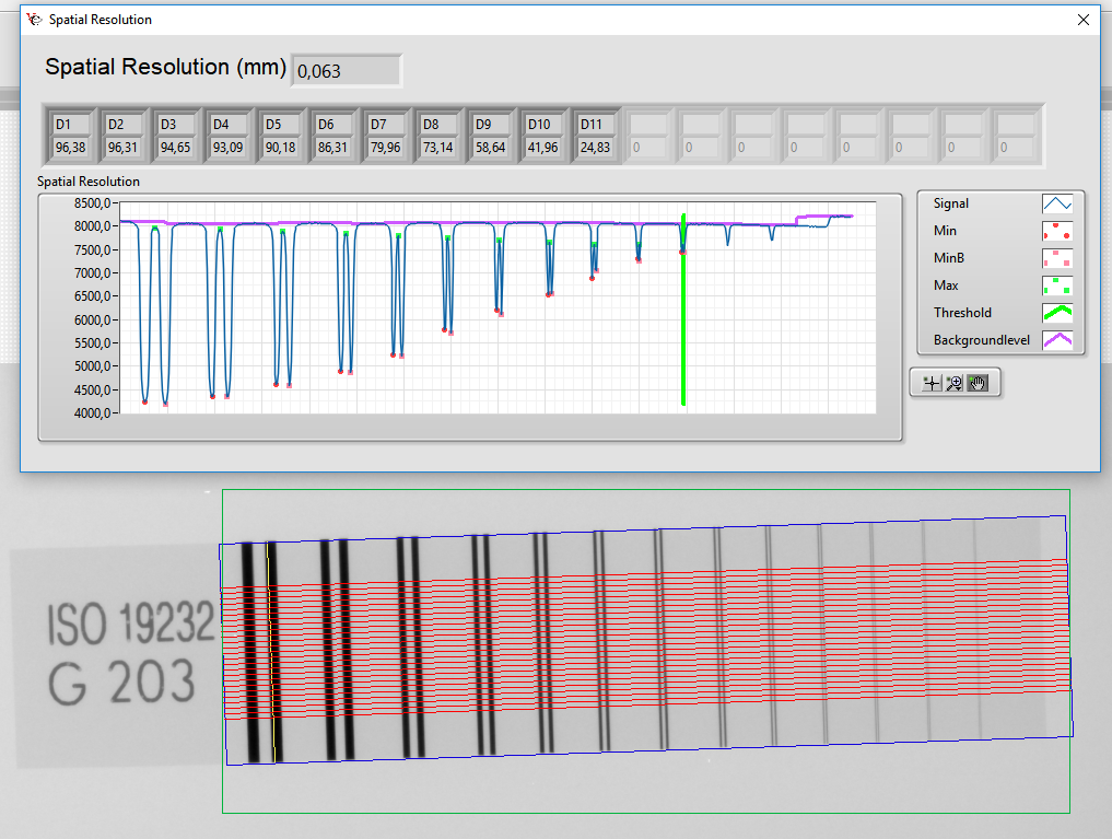
- Spatial Resolution (SRb):
The resolution is one of the most important values for the performance evaluation of an X-ray system. The readout electronics of the digital detectors (DDA, Digital Detector Array, matrix detector or flat panel detector) determines the pixel size. Modern detectors have pixel sizes of 25 – 200 µm. The thickness and type of the so-called scintillators (X-ray excitable light-emitting layer on the read-out electronics) also decisively determine the resolution of flat panel detectors. For thicker scintillators, there is more scattering within the luminescent layer, so in the worst case, for example, a 100µm pixel size detector may have a higher resolution than a 25µm detector with a thick scintillator layer.
The resolution is measured using a double-wire IQI (Image Quality Identifier), a test specimen with smaller and smaller wire pairs, whose indentation is measured using a line profile. It’s searched for the first wire pair, where the dip between two wires is less than 20% (see Figure 1: Spatial Resolution measurement with double-wire bridge). The associated resolution can be read from a table.

Figure 1: Spatial Resolution measurement with double wire bridge
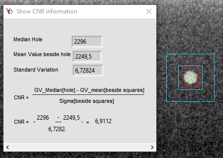
- Contrast noise ratio (CNR):
The contrast in the X-ray image can be determined through a single wire IQI or hole type IQI. In aerospace environments, hole test specimens to ASTM E1742 / E1025 have prevailed. These specimens have a defined thickness and 3 holes where the diameter of holes corresponds to the single (1T), double (2T) and quadruple (4T) specimens thickness. Depending on the thickness of the irradiated component, the corresponding specimen is selected. In this example 4T is selected and the mean gray value of the 4T hole is subtracted from the mean gray value on the specimen (IQI) and divided by the standard deviation (see Figure “: CNR measurement in the 4T hole).

Figure 2: CNR measurement in the 4T hole
The resulting value must be at least 2.5 to obtain a sufficiently contrasting image. The contrast sensitivity (CS) can be additionally calculated from this value.
- Signal to Noise Ratio (SNR):
The signal to noise ratio describes the distance of the interference signal to the useful signal. The SNR is calculated from the mean gray value divided by the standard deviation in a homogenous defined range. This value gives with a factor for the achieved resolution the normalized signal to noise ratio (SNRn). Higher SNR values allow greater visibility of the errors and the images are visibly smoother. The way to improve SNR is to increase image integration.
After selecting the right X-ray tube detector combination for the present application, it is essential for the aviation industry that the performance levels achieved at the beginning continue to be achieved permanently. This must be checked daily or even before each shift. For this reason, it’s worked with so-called test phantoms. There are several types of phantoms:
- Duplex Plate Phantom according to ASTM E2737: This is a two-stage phantom, one plate corresponds to the thinnest thickness, the other plate corresponds to the thickest thickness to be tested. Placed on it are a double-wire bar and the two matching hole test pieces according to ASTM. The test parameters (kV/mA, focal spot size, pre-filtering, geometric magnification, detector mode, number of image integrations, exposure time) should be those of the later test. This phantom can be made individually according to the needs (size, thickness and material).
- 5-Groove-Wedge according to ASTM E2737: This is a standardized specimen. There are two versions: Heavy metal or light metal. Using the milled grooves, it is possible to determine the different thicknesses, the resolution and the contrast sensitivity.
- TAM Phantom: This is a special made phantom that covers the testing of titanium and Inconel parts up to ¼ inch. At levels of 0.05 to 0.25 inches, the respective test specimens are in accordance with TAM ASTM E1742. The resolution is determined by two double-wire webs.
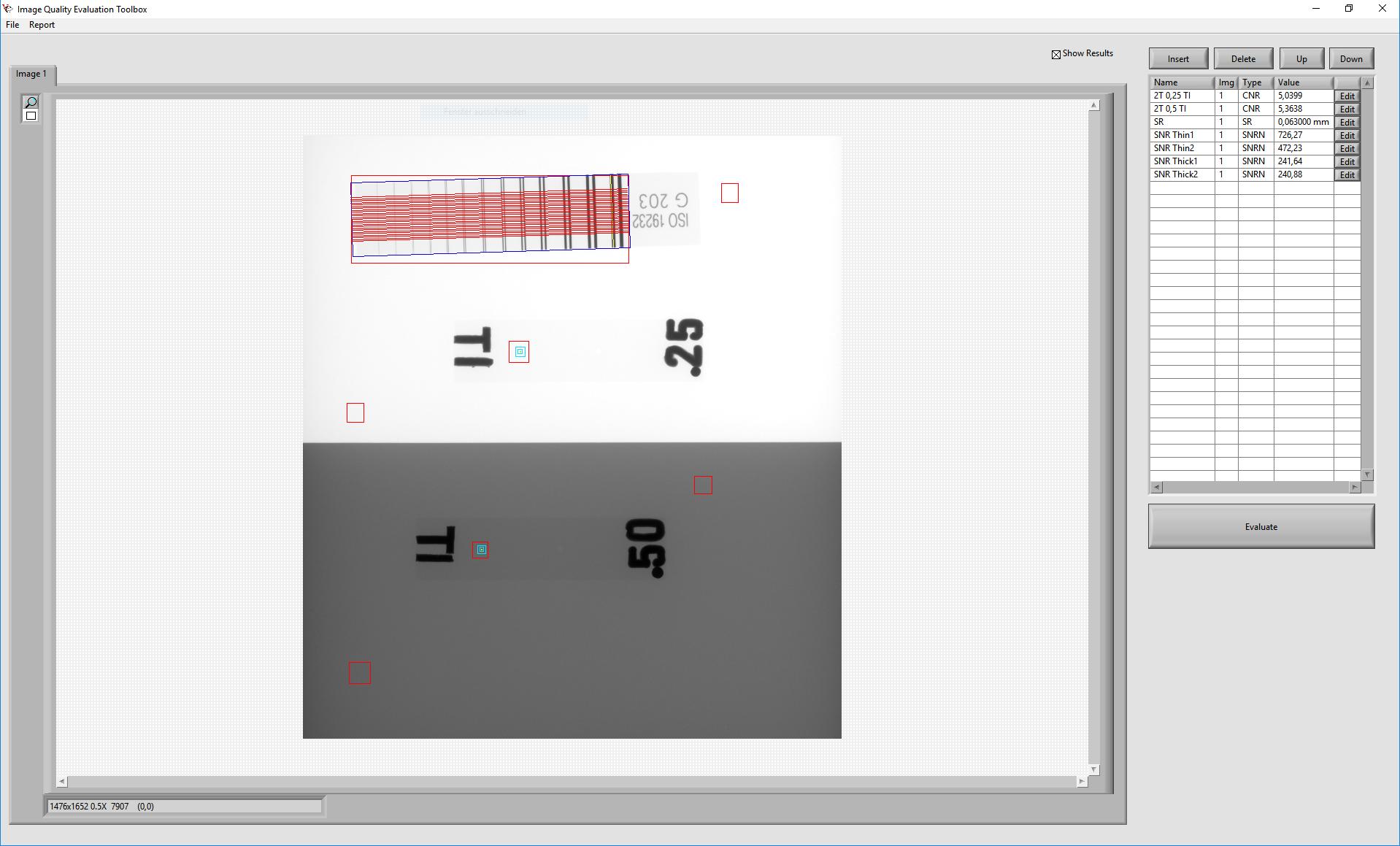
By using CNC-controlled equipment, such as XRH222, XRH111 or XRHGantry from VisiConsult, these daily image quality tests can be completely automated. The Xplus Image Quality Evaluation Toolbox automates repetitive checks. Values such as CNR, SNRn, SR, SL (Signal Level), CS can be generated wit one click (see Figure 3: Image Quality Evaluation Toolbox with Duplex plate Phantom) and saved as a report.

Figure 3: Image Quality Evaluation Toolbox with Duplex Plate Phantom
Also, for the detector calibration there are special requirements. Each flat panel detector must have a dark image calibration and white image calibration. In addition, there are so-called bad pixels on the detector. A classification of bad pixels is given in ASTM E2597 and there is also a standardized procedure to identify and classify them, although an accumulation of bad pixels can lead to the detector having to be replaced or an evaluation isn’t allowed to take place in this area anymore. The VisiConsult Xplus also offers a simple tool with the ASTM E2597 Dead Pixel Detection Tool to detect and classify bad pixels and to generate a report with one click and after a single parameter determination (see Figure 4: ASTM E2597 Dead Pixel Detection).
Figure 4: ASTM E2597 Dead Pixel Detection
The storage of digital images is based on a standard that was originally developed for medicine. With DICOM (or for the industry DICONDE) images, not only the uncompressed X-ray image but also process data are saved, which can be displayed again with a DICOM / DICONDE compatible image viewer.